This blog will take you through the steps required to plan a fan of underground drillholes within Leapfrog Geo and ensure that both collar and target points are snapped to.
Planning underground drillholes is critical to the continued operation of any underground mine and often requires navigating around existing development, infrastructure, and operational requirements.
It is essential that these holes are planned in the correct location, sometimes there isn’t much room for deviation or error. Drill sites may not be ideal and often the angle to the drill target is sub-optimal.
In order to save time and money we regularly plan a fan of holes from one collar location. It is important to consider drill rig specification and physical limitations regarding angles and depths, as well as the ease of manual handling for drillers.
This workflow will use existing underground development and ensure that both the collars and targets are snapped to the correct location. For the basics of drillhole planning, please see our blog: Drillhole planning in Leapfrog Geo.
Step 1: Identify the drill target
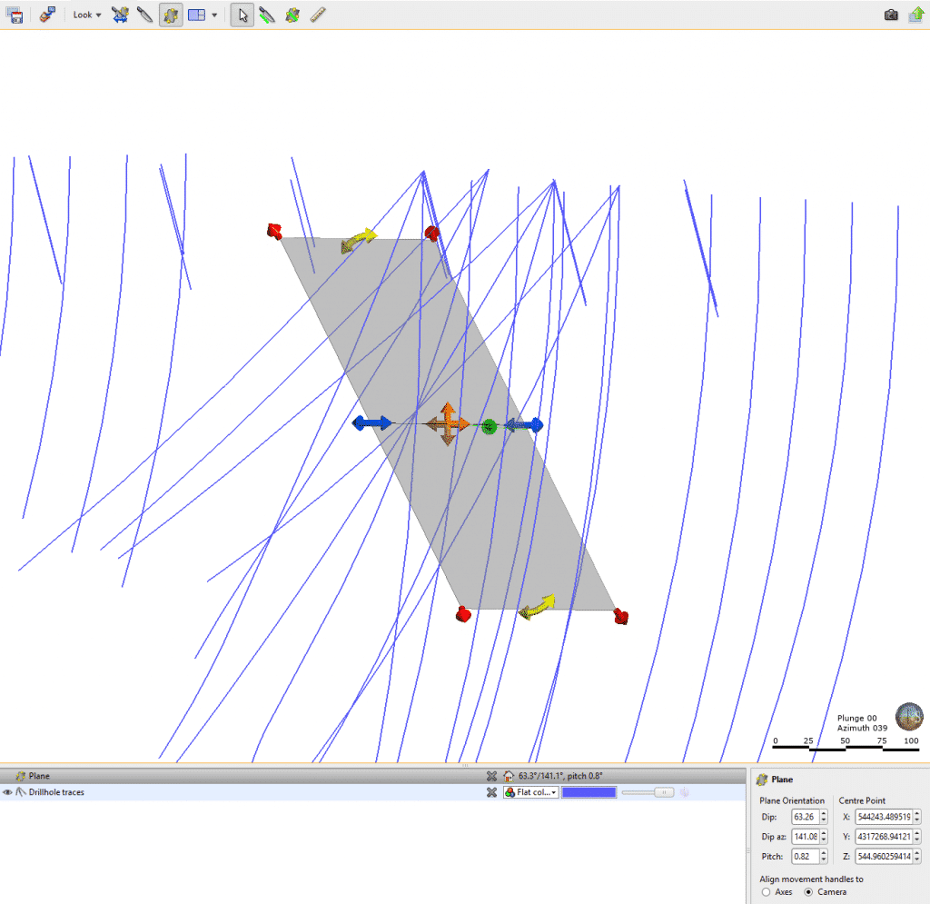
In this case we are using a mesh created from a moving plane to represent the target. In practice, this could be your mineralisation or geological wireframes.
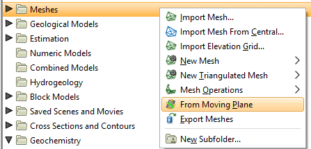
After drawing the plane in the 3D scene, right-click on the ‘Meshes’ folder and select ‘From Moving Plane’.
Step 2: Visualise existing drillhole spacing on target plane
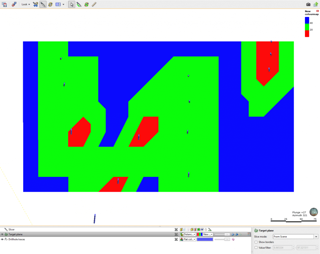
View the existing drillholes and assess where infill is required to meet the specified spacing; for example, grade control or reserve definition.
To help with this process we can use Leapfrog Geo’s distance function to create a buffer from existing drill traces to quantify these areas that need additional drillholes.
Step 3: Draw target points on the target plane
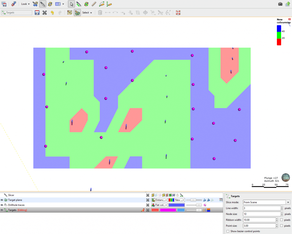
Create a new polyline and draw a point at each target location on the target plane. In the image above, the potential target areas > 40m from an existing drillhole are shown in blue.

Step 4: Draw collar points on the drive
Next, we want to locate a suitable collar location. We have a polyline that represents the outline of the drive. We will draw a point at the collar location on the drive or choose multiple collar location points if required.
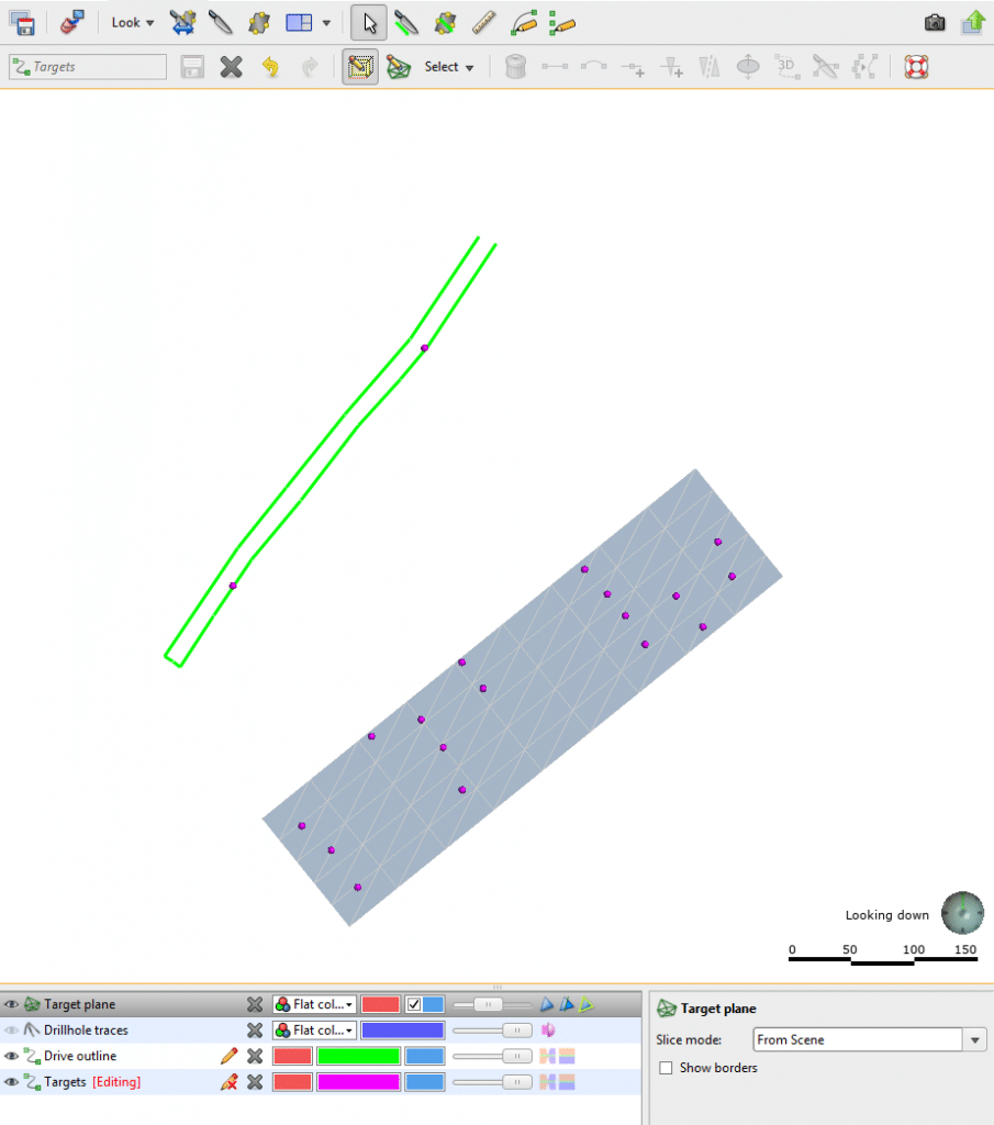
Once we have our collar and target locations ready, we will hide the target mesh and all other objects in the scene view and ensure that there is no slicer activated in the scene.
Now that we have all our information available, we can commence our drill design using the ‘Planned Drillholes’ feature.
Step 5: Plan the drillholes using the digitised target and drive collar points
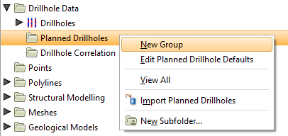
Right click ‘Planned Drillholes’, then select ‘New Group’.
Choose a name for your group and add any prefix you need for the planned holes.
Click ‘Add Drillhole’ to begin your first hole.
Specify the collar location and select the pointer. Click and drag from the collar point to the first target point and release the mouse. Remember to ensure that you don’t have any other objects in the scene so that you can snap to the points you have drawn.
Add an additional length into the ‘End of hole is ____ units past target’ and click ‘OK’.
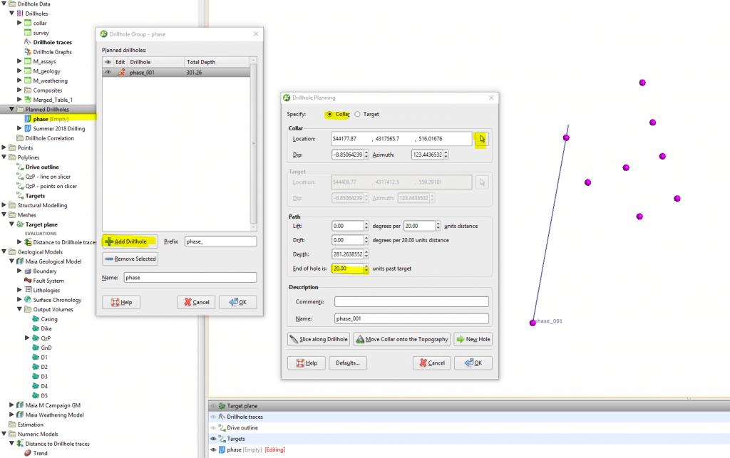
Hide the first hole from the scene view and select ‘Add Drillhole’ again.
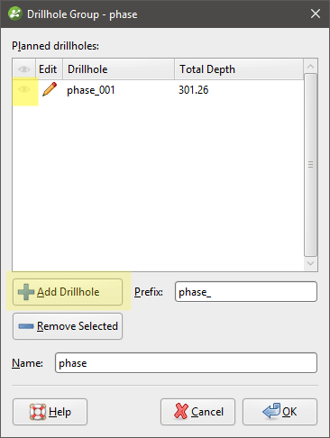
Repeat this process for each target point. Each time, ensure that all other drillholes are hidden so that the collar and target are snapped correctly for each planned hole.
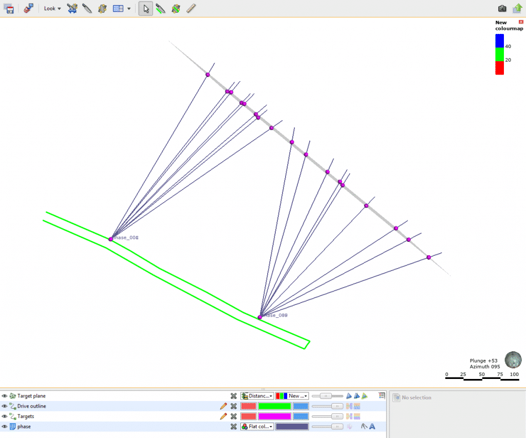
Step 6: Add planned holes to distance function
Finally, the drill plan can be validated by adding the new planned drillholes into the distance function to see if all areas have been infilled adequately.
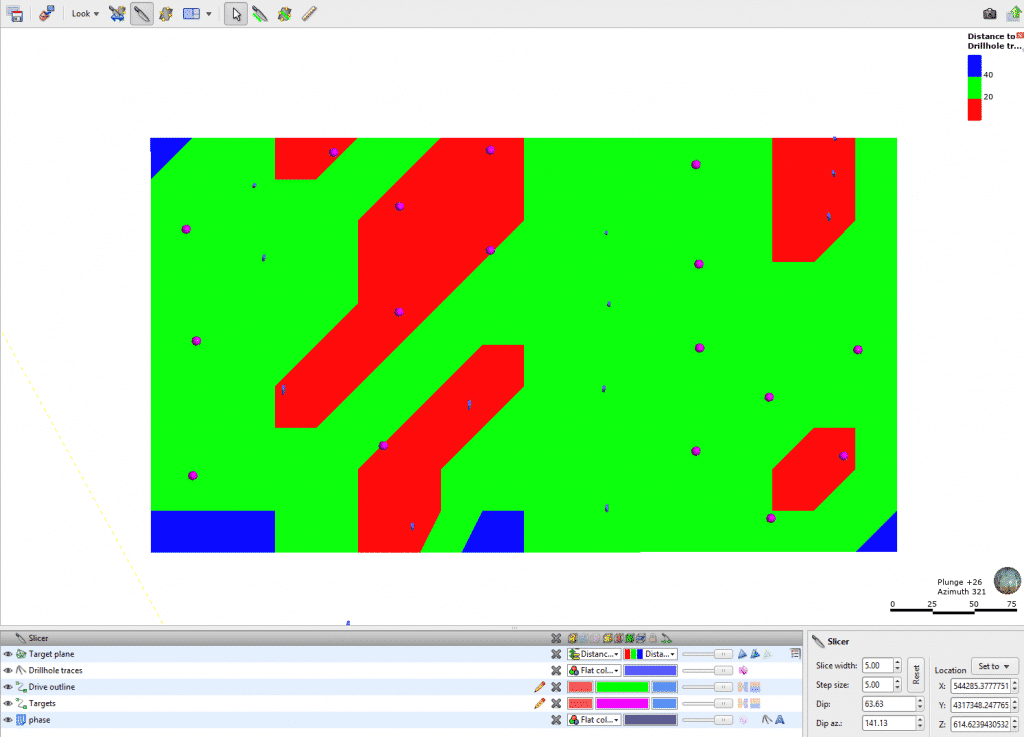
Using the distance function to help select the target locations based on our current data distribution provides a visual benefit. It also gives the confidence that appropriate drillhole spacing has been achieved while optimising our drill program and making the most of budgeted drill meters.


